Showing posts with label chapter 13. Show all posts

Monday, 25 May 2020

Chapter 13 // Exercise 19 - Principles & Practice Using C++

In this exercise I am using Visual Studio 2017 and the graphics files found here:
https://github.com/l-paz91/principles-practice/tree/master/Graphics%20Files

Chapter 13 // Exercise 19

Define a class Star. One parameter should be the number of points. Draw a few stars with differing numbers of points, differing line colours, and differing fill colours.

Github: https://github.com/l-paz91/principles-practice/tree/master/Chapter%2013/Exercise%2018


For this one, I decided that the minimum number of points needed was 5. After that, I found a chapter from a book called "Connections: The Geometric Bridge Between Art and Science" by Jay Kappraff. They explain that any polygon with 5 or more vertices can be used to create star polygons by extending the lines of each side till they intersect.

I also found this excellent video https://www.youtube.com/watch?v=omsNTaNLvAA which shows how to create stars from regular polygons by skipping vertices n number of times for each polygon. This video also helped visualize the difference between a real star polygon and a degenerate star polygon.

In the end though I decided to use a function I created in an earlier exercise that finds any point on a circle given an angle. Given the number of points, each point is  angle away from each other. So I can tell this function to keep retrieving me new points until we have enough to make the star.

Chapter 13 // Exercise 19 - Principles & Practice Using C++

Chapter 13 // Exercise 19 - Principles & Practice Using C++

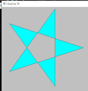
This works perfectly with real star polygons, however the draw_lines() function needs to be modified to fill the star in. It doesn't work for degenerate star polygons though. After some thinking I decided to go a bit simpler and create an outer circle and an inner circle. Then advance the rotation by n degrees each time selecting points alternatively on the outer and inner circle and then connecting them up. Not only does this allow 4 pointed stars but it works with both real star polygons and degenerate star polygons and draw_lines() doesn't have to modified:
Chapter 13 // Exercise 19 - Principles & Practice Using C++
(EDIT - please ignore the inner circle in this photo, it has nothing to do with the inner circle of the star...I just forgot to remove it)

I also changed the constructor so you can change the outer/inner radii and added a starting angle so you can rotate the star:
Chapter 13 // Exercise 19 - Principles & Practice Using C++


Sunday, 24 May 2020

Chapter 13 // Exercise 18 - Principles & Practice Using C++

In this exercise I am using Visual Studio 2017 and the graphics files found here:
https://github.com/l-paz91/principles-practice/tree/master/Graphics%20Files

Chapter 13 // Exercise 18

Define a class Poly that represents a polygon but checks that its points really do make a polygon in its constructor. Hint: You'll have to supply the points to the constructor.

Github: https://github.com/l-paz91/principles-practice/tree/master/Chapter%2013/Exercise%2018


At first I thought he just meant check that the points are a Polygon and I was "the code already does that" however the problem comes in supplying points in the constructor. We don't know how many points will be supplied which means that the constructor needs to take in a initialiser_list<> which can be of any size. There's already a constructor of this type in the main base class Shape. As Poly derives from Shape we can use this constructor, however there was no definition so I quickly added it:
If you've ever initialised a vector like this:
vector<int> v{1, 2, 3, 4, 5, 6, 7, 8, 9 };

Then you've used the initializer_list<> without realizing it. It's a great tool in the std library to allow you to initialise an object with an undetermined amount of items. Of course I'd recommend declaring the size wherever possible for the best performance.

The next thing to do is give open_polyline this constructor as you can only inherit from direct base classes. In this case the direct base class for Poly is Open_polyline whose base is Shape.

Once this is done, default constructors will need to be added to each class to remove any errors. 


Saturday, 23 May 2020

Chapter 13 // Exercise 17 - Principles & Practice Using C++

In this exercise I am using Visual Studio 2017 and the graphics files found here:
https://github.com/l-paz91/principles-practice/tree/master/Graphics%20Files

Chapter 13 // Exercise 17

Do the previous exercise, but using hexagons of a few different colours.

Github: https://github.com/l-paz91/principles-practice/tree/master/Chapter%2013/Exercise%2017

I was very sneaky on this one, mainly because the current hexagon tile function doesn't allow for hexagon colours to be changed easily. It would require a function re-write but this does the job.

Chapter 13 // Exercise 17 - Principles & Practice Using C++

Friday, 22 May 2020

Chapter 13 // Exercise 16 - Principles & Practice Using C++

In this exercise I am using Visual Studio 2017 and the graphics files found here:
https://github.com/l-paz91/principles-practice/tree/master/Graphics%20Files

Chapter 13 // Exercise 16

Do the previous exercise, but with hexagons.

Github: https://github.com/l-paz91/principles-practice/blob/master/Chapter%2013/Exercise%2016

I'm not going to re-write the hexagon tile function I wrote but instead just keep supplying it with the number of hexagons needed to tile the window. It does require some maths based on the radius but it's not time consuming.

Chapter 13 // Exercise 16 - Principles & Practice Using C++

Wednesday, 20 May 2020

Chapter 13 // Exercise 14 - Principles & Practice Using C++

In this exercise I am using Visual Studio 2017 and the graphics files found here:
https://github.com/l-paz91/principles-practice/tree/master/Graphics%20Files

Chapter 13 // Exercise 14

Define a right triangle class. Make an octagonal shape out of eight right triangles of different colours.

Github: https://github.com/l-paz91/principles-practice/tree/master/Chapter%2013/Exercise%2014


I really wanted to make a function that could draw any polygon with triangles but it required way to much brain power and at this point in the evening I've had quite a bit to drink and can't be bothered so I'm just going to brute force it. I was also confused because I kept thinking of a Regular octagon and seriously wondered if you could even make a regular octagon out of right triangles. I googled this high and low and managed to find this thread of someone doing the same exercise: 
http://forums.codeguru.com/showthread.php?545831-Making-an-octagon-out-of-right-triangles

An image of a regular octagon made out of right triangles is shown but there are arguments as to whether this is correct or not. So I thought, why not make the constructor throw an error if one of the angles in the triangles is not 90 degrees? Turns out determining the angles of intersecting lines is a bit more complicated then I thought.

I eventually found this post which made sense. I can't stand it when they use things like slope and r1 and squiggly symbols. I have no idea what any of that means, maths stack overflow is my worst nightmare:
https://stackoverflow.com/questions/3365171/calculating-the-angle-between-two-lines-without-having-to-calculate-the-slope

With this though I managed to give RightTriangle a function that gets the angle between 2 lines. You do need to input the points in a certain way when creating the triangle (the right-angle should always be the second point) but it is possible to create an octagon with all right-angled triangles; but it is not possible to create a regular octagon out of all right-angled triangles. 


Tuesday, 19 May 2020

Chapter 13 // Exercise 13 - Principles & Practice Using C++

In this exercise I am using Visual Studio 2017 and the graphics files found here:
https://github.com/l-paz91/principles-practice/tree/master/Graphics%20Files

Chapter 13 // Exercise 13

Draw the colour matrix from section 13.10, but without lines around each colour.

Github: https://github.com/l-paz91/principles-practice/blob/master/Chapter%2013/Exercise%2013

For this one, I simply set the line visibility to false. I remember having to change this function as it wasn't working properly so make sure to grab an updated copy of the graphics.h and graphics.cpp from a newer exercise.


Monday, 18 May 2020

Chapter 13 // Exercise 12 - Principles & Practice Using C++

In this exercise I am using Visual Studio 2017 and the graphics files found here:
https://github.com/l-paz91/principles-practice/tree/master/Graphics%20Files

Chapter 13 // Exercise 12

Draw a circle. Move a mark around on the circle (let it move a bit each time you hit the "Next" button).

Github: https://github.com/l-paz91/principles-practice/blob/master/Chapter%2013/Exercise%2012


.


Chapter 13 // Exercise 12 - Principles & Practice Using C++

(imagine this moving around)

Sunday, 17 May 2020

Chapter 13 // Exercise 11 - Principles & Practice Using C++

In this exercise I am using Visual Studio 2017 and the graphics files found here:
https://github.com/l-paz91/principles-practice/tree/master/Graphics%20Files

Chapter 13 // Exercise 11

Draw a 300-by-200-pixel ellipse. Draw a 400-pixel-long x axis and a 300-pixel-long y axis through the center of the ellipse. Mark the foci. Mark a point on the ellipse that is not on one of the axes. Draw the two lines from the foci to the point.

Github: https://github.com/l-paz91/principles-practice/blob/master/Chapter%2013/Exercise%2011

The first thing I did was google what a "Foci" was. Apparently it is the "focus points" of an ellipse. On a circle the focus points are dead center. One thing I had to keep in mind is that the foci lie on the major axis. The major axis is the axis that is the longest, so they could change between X and Y depending on the width/height of the ellipse.

Most formulas only tell you how to find the foci given that the center point is 0,0. However, our center point is 0+x, 0+y. I then realised that maybe I should not drink bacardi and pineapple when I'm programming because it took me 40 minutes to realise that the ellipse class already has the functions to find the foci.

In a previous exercise I already made a function to find any point on an ellipse given an angle, so the rest fell into place.


Saturday, 16 May 2020

Chapter 13 // Exercise 10 - Principles & Practice Using C++

In this exercise I am using Visual Studio 2017 and the graphics files found here:
https://github.com/l-paz91/principles-practice/tree/master/Graphics%20Files

Chapter 13 // Exercise 10

Define a class Regular_Polygon. Use the center, the number of sides (>2), and the distance from the center to a corner as constructor arguments.

Github: https://github.com/l-paz91/principles-practice/tree/master/Chapter%2013/Exercise%2010

Chapter 13 // Exercise 10 - Principles & Practice Using C++

I assume "distance from center to a corner" means the radius of the outer circle of a Polygon. I wish we had done this one as Exercise 9 as then I could've just made Regular_hexagon a child of Regular Polygon. 

I decided to do that and it got me thinking about a universal "tile" function for any type of polygon, however I want the tile function to remain static so that you can call it without actually having to have an instance of the object and you can't have virtual static functions in c++.

Friday, 15 May 2020

Chapter 13 // Exercise 9 - Principles & Practice Using C++

In this exercise I am using Visual Studio 2017 and the graphics files found here:
https://github.com/l-paz91/principles-practice/tree/master/Graphics%20Files

Chapter 13 // Exercise 9

Tile a part of the window with Regular_hexagons (use at least eight hexagons).

Github: https://github.com/l-paz91/principles-practice/tree/master/Chapter%2013/Exercise%209

With this I wasn't sure if I should give the tiling a boundary, like a 400x400 area to tile and you pass in that area into a constructor. Or if I should push a load of hexagons back into a vector and change the x/y positions with each hexagon. I decided on giving a boundary. When you tile a hexagon, there should be no spaces in-between which makes it easy to determine where the next hexagon should be.

Considering we draw the hexagon from the center with a given radius, that means on the x axis, the next hexagon center point should be 2 radii + a side length away. On the y axis, the next hexagon center point is an apothem away. The apothem is the radius of the incircle of a polygon. 

To find the side length of a polygon, use the formula:
sideLength = 2Radius * sin(PI/numOfSides);

The apothem:
apothem = radius * cos(PI/numOfSides);

Chapter 13 // Exercise 9 - Principles & Practice Using C++

To get the hexagons to draw at different x values on a new line I used a simple flipflop:

Chapter 13 // Exercise 9 - Principles & Practice Using C++

Here, flipflop is a bool set to 0. When x becomes more than the edge, the flipflop is inverted. So if flipflop is true, !flipflop is false and then !flipflop again becomes true. We want the x co-ordinate to always be either 0 or (radius + half sideLength). If you multiply an int by a bool it will either be 0 or the number you want. This reduces the amount of branching the cpu has to do.

Tuesday, 12 May 2020

Chapter 13 // Exercise 8 - Principles & Practice Using C++

In this exercise I am using Visual Studio 2017 and the graphics files found here:
https://github.com/l-paz91/principles-practice/tree/master/Graphics%20Files

Chapter 13 // Exercise 8

Define a class Regular_hexagon (a regular hexagon is a six-sided polygon with all sides of equal length). Use the center and the distance from the center point as constructor arguments.

Github: https://github.com/l-paz91/principles-practice/tree/master/Chapter%2013/Exercise%208


Seeing as how in Exercise 11 of the last chapter I already made a function that can produce any regular polygon given a radius and number of sides, this was quite simple to adapt the code.


Saturday, 2 May 2020

Chapter 13 // Exercise 7 - Principles & Practice Using C++

In this exercise I am using Visual Studio 2017 and the graphics files found here:
https://github.com/l-paz91/principles-practice/tree/master/Graphics%20Files

Chapter 13 // Exercise 7

Make and RGB colour chart (e.g., search the web for "RGB colour chart").

Github: https://github.com/l-paz91/principles-practice/blob/master/Chapter%2013/Exercise%207


This was perhaps one of my favourite exercises so far as it was something I actually wanted to know how to do but always got overwhelmed when I tried to when picking a language/api.


I currently have a program that converts 24 bit bitmap images to SNES format however, it's only a command window program at the moment. One of the upgrades I wanted to add was the ability to change your colour palettes by selecting from a colour chart. I was going to do a C# winforms program however, I feel confident that I could get the program done now using FLTK and C++ which is great because I hate C#.

As a little bonus I decided to write a program that draws the full colour palette that the SNES can use. The SNES uses 15-bit GBR. It's not 16-bit RGB because Nintendo*. This means there is 32,768 colours that the SNES can display (not all at once though). I think this is known as 'high-color'. Either way, here they are:


This took me several days to wrap my brain around; colour is hard. It took me a while to figure out the name of what I trying to do. Apparently I wanted to make a 7 colour gradient heatmap. I eventually settled on this wiki here, that shows how to create a colour gradient class:
http://www.andrewnoske.com/wiki/Code_-_heatmaps_and_color_gradients

I changed a few things and added the ability to create different gradients based on how many colours you want. I also made options to create 15 bit gradients but they look pretty much the same. Instead of uploading that here I'm going to clean it up a bit and do a tutorial on how to add a Colour Gradient class to FLTK using Bjarne's suite of functions. I wanted to add black and white to the gradient map but I'm unsure how to do that just yet.

This link has nothing to do with anything really but I'm leaving it here because I know I'll forget where I've bookmarked it:
https://docs.microsoft.com/en-us/windows/win32/directshow/working-with-16-bit-rgb

*if you're interested it's because 65816 only accepts bytes that are 8 or 16 bit in length and 8 or 16 cannot be evenly divided by 3. Therefore, the high byte is padded with an extra bit. This extra bit is always set to 0 and the SNES expects it to be 0. Some people assume this bit is used for alpha (aka transparency) however it is a single bit; either on or off and therefore can't convey how much transparency is needed, so it is simply just for padding. 

Monday, 27 April 2020

Chapter 13 // Exercise 6 - Principles & Practice Using C++

In this exercise I am using Visual Studio 2017 and the graphics files found here:
https://github.com/l-paz91/principles-practice/tree/master/Graphics%20Files

Chapter 13 // Exercise 6

Write a program that draws a class diagram like the one in Section 12.6. It will simplify matters if you start by defining a Box class that is a rectangle with a text label.

Github: https://github.com/l-paz91/principles-practice/tree/master/Chapter%2013/Exercise%206


I originally decided to derive the Box class and add text to it, however it proved a little cumbersome. So instead, I derived the Text class and gave it a Box as a member variable. The only difficult part was giving the box the correct length. I tried searching the FLTK documentation however there is no way to get the full length the Text string. There is a function called fl_width() which takes in a char and calculates the width of it in pixels using the font size given however, it always returned -1 for me so I don't think it works properly. So instead, I made the width the number of characters multiplied by the font size. It isn't perfect but it ensures the text box is always big enough.


EDIT 12/05/2020
So I found out the reason fl_width() is returning -1 is because the font_descriptor() is null in the graphics driver. This is because the font is never actually set, we just call the default Font constructor in Text::draw_lines().

To enable fl_width() to work the font must be intialised in the text constructor. 


fl_width() then takes in a c-style string and determines the width of pixels in each character. This does not account for spacing though so in some cases the box may not encapsulate the text. for this I just added on some padding. Not perfect but close enough.


I provided a function in the Text class to be able to do this:


Friday, 24 April 2020

Chapter 13 // Exercise 5 - Principles & Practice Using C++

In this exercise I am using Visual Studio 2017 and the graphics files found here:
https://github.com/l-paz91/principles-practice/tree/master/Graphics%20Files

Chapter 13 // Exercise 5

Define the functions from exercise 4 for a Circle and an Ellipse. Place the connection points on or outside the shape but not outside the bounding rectangle.

Github: https://github.com/l-paz91/principles-practice/tree/master/Chapter%2013/Exercise%205


Following on from Exercise 4, Circle and Ellipse can now override the function in Shape. North, east, south and west are easy to draw for circle shapes from the center point and the other points can be easily obtained by using some trigonometry. You can just use the radius and given points to mark on the bounding box (Bjarne does allow it) but it's pretty simple to mark on the circle itself.

Ellipse is slightly different in that the radius can differ based on width/height.


Thursday, 23 April 2020

Chapter 13 // Exercise 4 - Principles & Practice Using C++

In this exercise I am using Visual Studio 2017 and the graphics files found here:
https://github.com/l-paz91/principles-practice/tree/master/Graphics%20Files

Chapter 13 // Exercise 4

Define functions n(), s(), e(), w(), center(), ne(), se(), sw(), and nw(). Each takes a Rectangle argument and returns a Point. These functions define "connection points" on and in the rectangle. For example, nw(r) is the northwest (top left) corner of a Rectangle called r.

Github: https://github.com/l-paz91/principles-practice/tree/master/Chapter%2013/Exercise%204

Thinking about it, this makes a lot more sense to have as operations inside the Rectangle class than outside. The next exercise wants the same functions to be able to work with circles and ellipses so I decided to stick them in Shape. After some thinking and typing out all the function declarations, I figured there would be quite a bit of code duplication so I decided to create an enum of Point Directions that you can pass into one function and it returns the correct Point.

For a Circle and an Ellipse, the first initial point is the center whereas for a Rectangle its the top left. Instead of doing a dynamic_cast to determine what type of shape we are dealing with and then selecting on that; I decided to make the function virtual so a derived type can override it with it's own code if they wish.

Bjarne hasn't explicitly mentioned virtual and overriding outside a few brief mentions, but we are using that type of code so I don't consider it too advance for this stage.

In order to display all the marks I had to modify the graph files a bit as the Mark class was deriding from Marks which derides Marked_Polyline. This meant that all the marks were drawing lines between them which only Marked_Polyline should be doing. I uncommented the version of Marks below Mark and renamed it and did the same for the Marks::draw_line() function in Graph.cpp. 


Wednesday, 22 April 2020

Chapter 13 // Exercise 3 - Principles & Practice Using C++

In this exercise I am using Visual Studio 2017 and the graphics files found here:
https://github.com/l-paz91/principles-practice/tree/master/Graphics%20Files

Chapter 13 // Exercise 3

Define a class Arrow, which draws a line with an arrowhead. 

Github: https://github.com/l-paz91/principles-practice/tree/master/Chapter%2013/Exercise%203


Again, I wanted to give a way to adjust the size of the arrow head so this took a little longer as I thought about it. Then as I spent a few hours banging my head against the wall I began to realise that this would take quite a bit of maths to solve. But I didn't know what maths. After more hours of googling I came across this stack overflow post which started to make some sense:
https://stackoverflow.com/questions/10316180/how-to-calculate-the-coordinates-of-a-arrowhead-based-on-the-arrow

I knew there had to be some vector stuff involved as when I went down the trigonometry route; I discovered that the two "back points" could potentially be infinite between the mid-base point of the triangle and the tip.

With vectors though (not std::vector), the direction of the arrow helps narrow down those two back points. Eventually I came across this post:
https://math.stackexchange.com/questions/927802/how-to-find-coordinates-of-3rd-vertex-of-a-right-angled-triangle-when-everything?rq=1

Which started to give me some actual formulas and "normal-ish" words to try and figure out what I had to do. And then I found this post off the side of it:
https://math.stackexchange.com/questions/2125690/find-coordinates-of-3rd-right-triangle-point-having-2-sets-of-coordinates-and-a

This link was the jackpot. Thank you Stack Exchange user Futurologist, you're a genius. This formula was exactly what I had been looking for.

Here is one of the arrows drawn by my program (with some annotations in paint):


We know the locations of the following points:
x1, y1 == p1.x, p1.y
x2, y2 == p2.x, p2.y
x3, y3 == p3.x, p3.y

I wanted the arrow tip to be at P2 with each side of the arrow to have a length of arrowSize. Point 3 was found by using a formula to find a point on a line given two points, the full distance and the distance away from Point 2.

The exact formula above produced the correct Y results but the X ones were a little off. I figured it was because the triangle was slightly different. I ended up using Point 3 (instead of x2,y2) to get the co-ordinates I was looking for. This gave me the left hand corner and to get the right; I simply reversed the P1 and P2 coordinates.

I started this at 4pm and just finished writing this post at 12:30am. At least I've learnt something extremely useful.

The arrow can change size, have a different fill colour to line colour, have the line style changed to dashes/dots, and increase/decrease the weight of the line; whatever takes your fancy.

Tuesday, 21 April 2020

Chapter 13 // Exercise 2 - Principles & Practice Using C++

In this exercise I am using Visual Studio 2017 and the graphics files found here:
https://github.com/l-paz91/principles-practice/tree/master/Graphics%20Files

Chapter 13 // Exercise 2

Draw a box with rounded corners. Define a class Box, consisting of four lines and four arcs.

Github: https://github.com/l-paz91/principles-practice/tree/master/Chapter%2013/Exercise%202


This could've been done quickly however I wanted to be able to give users a way of adjusting the 'roundness' of the corners and I was stumped (I'm not good at this type of stuff...I just like to make things go faster). I got it wrong a couple of times due to not taking the time to understand how  fl_arc() draws.


The arc is basically determined by the radius of the circle it calculates, so by supplying a "roundness" variable we can use that to get the radius of the arcs (by simply dividing it by 2). Perhaps a better name for it would be "Circle Width" but I don't think and end user would find that useful.

The cyan box was given a 'roundness' of 20 and the black box 100. Fl_arc() really confused me in this because I didn't stop to think about the point at where each arc was being drawn from. Fl_arc() simply draws a portion of a given circle from the top left hand corner. So that would mean our top right-hand arc x,y co-ordinates lie before the end of the top vertical line (exactly the end minus the radius). 

When drawing the lines, they use the position of the arcs (plus either the radius or roundness) to determine the length/height they should be; thus allowing them to adapt to tighter corners (but not exceed the width/height supplied).

A quick note on fl_arc as well. Fl_arc() requires you to give two angles (with the first smaller or equal to the second). If you imagine a clock face, FLTK draws an arc clockwise with 3 being 0 (for some odd reason). So the top left-hand arc would be the angles 90 to 180 (or 9 to 12).

To fill in the box, fl_pie() just needs to be supplied with the same data given to fl_arc() and then draw 3 rectangles using fl_rectf().


Sunday, 19 April 2020

Chapter 13 // Exercise 1 - Principles & Practice Using C++

In this exercise I am using Visual Studio 2017 and the graphics files found here:
https://github.com/l-paz91/principles-practice/tree/master/Graphics%20Files

Chapter 13 // Exercise 1

Define a class Arc, which draws a part of an ellipse. Hint: fl_arc().

Github: https://github.com/l-paz91/principles-practice/tree/master/Chapter%2013/Exercise%201


If you do a search for fl_arc in the current code you can see it's already used in the Circle and Ellipse draw_lines(). It pretty obvious to just copy the class code for a Circle or an Ellipse and simply call it the 'Arc' class. 

Don't do what I did though and forget to change the fill and color properties...I ended up drawing it off somewhere else and the fill just filled the entire circle. As Treebeard once wisely said "don't be hasty".


Wednesday, 1 April 2020

Chapter 13 // Drill 5 - Principles & Practice Using C++

In this exercise I am using Visual Studio 2017 and the graphics files found here:
https://github.com/l-paz91/principles-practice/tree/master/Graphics%20Files

Chapter 13 // Drill 5

Add a 100-by-100 image. Have it move around from square to square when you click the "Next" button. Just put wait_for_button() in a loop with some code that picks a new square for your image.

Github: https://github.com/l-paz91/principles-practice/blob/master/Chapter%2013/Drills/Drill%205


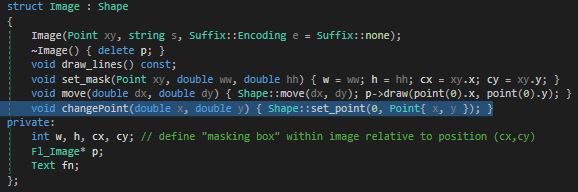
The move function doesn't actually do what I wanted it to do in this exercise as if you go look at it's implementation in Graph.h you'll see that it actually adds the given co-ordinates to the existing ones. I realised this when I was wondering where the image was while furiously clicking next; the x and y values were around 8000 and 9000 by that point. So instead, I just made a new function within the Image struct that allows you to re-set the points for the image. Shape has a set_point() function however it's protected which means that derived classes can only access it from within the class.


 (Imagine the doge jumping around...)